Pokazywanie postów oznaczonych etykietą data acquisition. Pokaż wszystkie posty

wtorek, 18 sierpnia 2020

OpenSPAD


OpenSPAD (Single Photon Avalanche Diode - fotodioda lawinowa do pomiaru pojedynczych fotonów) to otwarty detektor światła, działający na zasadzie zliczania fotonów przez fotodiodę lawinową pracującą w tzw. układzie Geigera z układem aktywnego gaszenia lawiny.

Projekt stworzony został przez elektroników z GaudiLabs [1], jako prosty w wykonaniu detektor zdolny do detekcji pojedynczych fotonów. Zastosowania takich detektorów są ogromne, głównie stosuje się je w nauce - w spektrometrii, mikroskopii, fizyce kwantowej etc. Dzięki temu, że układ ten jest w stanie wykryć pojedynczy foton i dokładnie zlokalizować go w czasie, diody tego typu stosować można także w eksperymentach czasoworozdzielczych, takich jak na przykład TCSPC (Time Correlated Single Photon Counting - czasowo skorelowane zliczanie fotonów) do mierzenia czasów zaniku barwników itp. lub HBT (Hanbury-Brown-Twiss, od nazwisk twórców metody) do korelacji emisji fotonów np. w celu wykrywania źródeł pojedynczych fotonów. O tych metodach bliżej może kiedy indziej. Teraz - kluczowy element - sam detektor fotonów.

środa, 5 sierpnia 2020

Projekty do szuflady? Czemu nie.


OpenSPAD - płytka w/g mojego projektu
Ostatnio tutaj nic się nie dzieje. Z przyczyn różnych: wykańczam dom, więc mam istotnie mniej czasu, na cokolwiek poza tym i pracą zawodową; ta ostatnia też mocniej niż zazwyczaj mnie pochłania. Dodatkowo, sezon rekonstrukcyjny chyba dokumentnie zdechł w tym roku - brak imprez jakichkolwiek średnio motywuje mnie do czegokolwiek w tym zakresie, a fakt, że część rzeczy pojechała już do nowego domu nie ułatwia mi zabranie się za jakąkolwiek robotę 😉.

Ale robię też ciekawe rzeczy. Szkoda, że większość związana jest z pracą i raczej się tutaj nie pojawi. Te niezwiązane bezpośrednio z pracą wynikają głównie z faktu, że a) uczę się nowego oprogramowania - KiCad; b) mam planach - pewnie dalekich - poskładanie kilku urządzeń wprost z labu fizycznego. 

Nauka softu do projektowania PCB jest o tyle przyjemna, o ile fajne projekty się robi - nie wyobrażam sobie jej inaczej, niż projektując ciekawe płytki. Dlatego też trochę projektów "do szuflady" właśnie powstaje lub niebawem powstanie. Część to urządzenia w/g projektów z sieci, ewentualnie zmodyfikowane przeze mnie, część to urządzenia od podstaw zaprojektowane przeze mnie. W najbliższym czasie zamierzam pokazać kilka z nich.

W międzyczasie bawię się także kilkoma dev-kitami, więc może i o nich coś niebawem napiszę. Mam na tapecie PSoCa (znowy!) i logikę programowalną, między innymi po to, by lepiej zaprojektować pewne systemy "do szuflady", a może i nie...


wtorek, 20 marca 2018

Impedance spectrometer


Some time ago I was showing 3D render of my impedance spectrometer project. It was planned for a competition on Elektroda.pl, but of course I massively misjudged the amount of time needed to finish the project (it is still not finished). So I cab shed some light on the device, I guess...

Impedance spectrometer is a device that measures the complex impedance - real resistance + imaginary reactance as a function of frequency. It is widely used in sensor applications, biosensing, electrochemistry and material sciences. We will talk about some of the applications later on, when the device will be finished and ready to perform some test measurements.

sobota, 21 października 2017

Jesienna aktualizacja

Po okresie wzmożonej aktywności pod koniec lata nadeszło jesienne uśpienie. Obroty zwolniły, a wraz z nimi tempo realizacji poszczególnych projektów i publikacji newsów na blogu. Nie oznacza to, że nic aktualnie nie robię.

sobota, 29 lipca 2017

Synchronizing inputs and outputs in DAQmx

I'm writing this simple tutorial mostly for myself, as I am tackling generally the same problem third time in my life, and third time I had to (re)invent the exact method how to do that. The problem is very basic: How to synchronize two (or more) outputs in inputs in a NI data acquisition setup, using DAQmx in LabVIEW? By synchronizing I mean e.g. a situation where we are sampling two outputs simultanosly or measuring some data in sync with a control output.

piątek, 16 sierpnia 2013

Mysterious hardware, part 3.

So finally I have obtained an ISA-equipped PC that would be relatively new (a industrial grade P4) that allowed me to install Win XP and LabView software in order to debug the card, or at least try to do that. The motherboard was kindly donated by an elektroda.pl user and blog-reader nicknamed music. Thank you!

Using a simple LabView software I tried to write and listen to/from the cards addresses (that I know, as I can configure the 7 MSB by jumpers). It is quite easy to do that, as LabView offers InPort and OutPort commands that allow me to directly talk to the bus. As I do not believe that it can be so easy I have hooked an oscilloscope to the cards address lines and address decoder output in order to check if it's working or not. And it is.

Unfortunately I did not get any response from the card. Two options are: the card (or cards CPLD at least) is dead or that the communication protocol is more complicated. I'm in favor of the latter. For now I have no further idea what to do with this piece of hardware apart from trying to read the CPLD content. As I do not have any cable for Lattice ICs and any proof that this approach will be valuable I just put the card back on shelve. At some point maybe I will come back - to further work with it or scrap it, as there are plenty of nice and rare ICs there.

piątek, 29 marca 2013

Short pulse generator, part 1.

Some time ago I have started designing an short pulse generator for time-resolved spectroscopy of electroluminescence. At first the design requirements were high, but after a market query, in search for devices capable of meeting these requirements they were lowered down significantly.

The sample for which this device is planned is a thin sheet of material suspended on an alumina frame, that acts as electrodes. We have measured DC I/V curve for the sample to assess the working parameters:


Therefore what we need is voltage of at least 35 V with current of at least 250 mA. In order to have an reserve in the parameters I assume that we need at least 40 V and 400 mA. For sake of simplicity I assume that the load of the device is almost purely resistive. Assesing the time parameters was a harder thing to do, so I assumes that the lower the better (the pulse time). Where is the limitation? In the power stage.

Using a simple generator, shown below, we are capable of generating a ~1 ns wide 5 V pulse with ease, using standard, from-the-shelf components. This could be even improved with faster ICs (comparators and AND gate.

From this Linear application note.

But this circuit generates only 5 V pulses (or close to that, this is the power supply voltage of the output AND gate). Also, the current is very limited - to 10 mA, offered by a TTL gate. In order to improve these parameters we have to add an output power stage, that will have output current and maximal voltage on the level of the planned device and could be controlled by an TTL pulse. To meet these requirements I have chosen several routes to achieve that:

  • A set of parallel bipolar transistor put in the common base topology. This should allow to achieve high rise and fall time of the pulse, but a current of a single fast transistor is low (tens of mA) so I need to put lots of them in parallel and I am not convinced that this is totally safe and will not affect the working of the device.
  • A (most probably single) FET/MOSFET device. An easy scheme for achieving high currents, even of hundreds of amps, but the pulse time will be significantly longer. With a dedicated driver and chip-to-pcb mount some people achieved 25 ns pulse width, although with a current of 100 A (as soon as I find the paper I'll post a link here). A stand-alone mosfet usually will have a rise time of several ns and fall time of 100 ns or more.
  • A dedicted IC. A RF power amplifier or a MOSFET driver. The first type of ICs seems to be a good idea as it offers tens of GHz in bandwidth, although when I have looked closer in this matter it seems that such IC will only work good in a typical circuit, for example an WiFi amplifier or so. On the other hand, some MOSFET drivers, are capable of almost meeting my requirements. EL7158 from Intersil is capable of producing 12 A pulses with rise and fall time of 12 ns (with 2000 pF load). This gives a chance to produce a 25 or shorter ns pulse, although the voltage is limited up to 18 V. Although this is not the only such driver on the market...
So currently I'm on the stage of parts requirements stage. As soon as I get something new I will post it here for sure.

wtorek, 26 marca 2013

VMEBus crate - why not.

Recently I have acquired an VME CPU-Card and thought about testing it somehow. As after powering it up the card seemed to be alive I have decided to give it a shot and try to put together an VME crate.

For that I have used an old Eurorack that I have got from some phone central (or some similar telecommunications equipment). After checking that the size of the crate is standard I bought an backplane from e-bay for... 1 Euro (plus 12 for shipping, but that's not the case). Unfortunately only this backplanes are so cheap, regular VME equipment is pricey as hell.

So i have started from taking apart the old backplane:

And putting the new one:

Sorry for the mess. You can see that here the backplane is already in position, and connected to a power supply (it takes 5 V and +/- 12 V). The PSU is also taken from the same equipment that the crate is.


This (above) is the CPU card (on the left) with the display controller removed, and the display controller itself (on the right). The CPU Card is an Pentium 120 MHz with 64 MB RAM equipped with Universe Tundra VMEBus controller. Fortunately there are plenty of drivers for this PCItoVME bridge. The cards equipment covers a wide range of peripherals - starting from two serial and one parallel port, going through VGA, Ethernet and finishing with SCSI-II. The card has two PCI-compatible slots, one of which is occupied by the display controller. It also has an PC/104, ISA compatible socket. The SCSI, together with the FDD connector are on the P2 connector of the VMEBus, so I will have to make a special connector going from the P2 on the backside of the backplane  to the SCSI harddrive. As far as I have tested the CPU-card is fully functional so after I get some free time I will try to connect an SCSI HDD to this setup and install some Linux maybe. After that I plan to go back to few years ago when I was studying and try to re-learn VHDL in order to make some VME cards for this setup


środa, 6 lutego 2013

Mysterious hardware, part 2.

Okay, so I had some spare time to tinker with the Analog I/O card. Unfortunatelly I do not have much info now:
  • On the DB50 connector on the bracket are signals from/to all the MUXes, this means 32 analog ports. Most probably analog inputs. The rest of the signals on the bracket connector is unknown.
  • The card is electrically okay. It did not crash the computer I have inserted it in.
  • the adressing uses only 10 bit, from which 7 MSB are to be configured by jumpers. This should help me to talk/listen to ports of the card.
Now this project is going a bit on hold. I have to obtain a motherboard with ISA connector and as powerful as possible (for the sake of convinience). I have locates several like that, so this is matter of time only. The problem is that I do not have any PC that 1) has OS on it, 2) is able to fit the card inside. And also - I would not like to test a '97 card on a '90 PC. It is hard without complicating it like that ;).

poniedziałek, 4 lutego 2013

Setup for optoelectronic characterization of nanostructures

So I managed finally to put together the setup for optoelectronic characterization of nanostructures, consisting of a wide-field fluorescent microscope that we have at work in the institute and my set of devices, namely the precise ammeter and electrode holders together with two power supplies (one for powering the ammeter, second one for polarizing the sample. Sorry for the low quality of photos, but I have only ma cellphone camera here at the moment.

Electrode holders are placed on a metallic plate (in order to fix them to the microscope using small neodymium magnets). The electrodes are made of sewing needles (cheap, easy to get and with a  sharp tip).


Here is the operator view of the whole setup. On the right there is also an PC that is collecting the data from the CCD camera in the microscope and from the picoammeter, using an National Instruments USB DAQ. On the right, next to the microscope, is the PSU used for polarizing the sample. It is capable of outputting up to 200 W or 40 V, whatever is lower at the current moment.


And here is the side view of the setup with the bug PSU powering the ammeter on the right, the ammeter and USB DAQ behind it. The computer controlling the whole thing is not shown here.


So stay tuned for some preliminary results (as soon as I obtain anything that is worth showing).

niedziela, 3 lutego 2013

Mysterious hardware, part 1.

Some time ago I have acquired this card. It has plenty of interesting ICs on it, so I though about buying it before thinking about any use of it or at lest checking if there are any manuals and/or drivers.


The card was produced by a german company disys GmbH. The manufacturer showed me a general middle finger by saying that this card is unsupported, the backup with manuals and drivers and any other possible documentation is gone/dead/broken buuuuuuuut they could possibly try to find the documentation if I pay around 500 euro. Come on - how greedy a company has to be and how messy it has to be inside to ask something like that. If you ask me, this does not tell any good about the company.

None the less I intend to, at least, try to make this card working again. In order to do this first I need to identyfy some kind of drivers for this device and then do whatever is needed to interface to it. I guess this is worth the labor, as this card seems to have various interesting features, judging by the ICs that are on board:


Lattice ispLSI1032 - a 60 MHz CPLD, together with several HCTs and PALs working as the glue logic I guess.  Also three FIFO CMOS Memory ICs (50MHz AM7210), what suggests that the card should has some fast input (up to 50 MHz I guess). The card also has two Nec D71054 CMOS 8MHz counters. There is an 74HCT688 address decoder, that is close to the address jumpers (not seen here). I hope this will allow me to get the card physical address in order to start debugging.


The analog section is quite interesting. The card is capable of having D/A (digital to analog) and A/D  (analog to digital) converters together with PGAs (programmable gain amplifier) and analog MUXes (multiplexer). Unfortunately not all sockets are filled. In the D/A section is completely empty (not counting a single transistor Q600 and three precise potentiometers TR600..602. The Q600 is an RFL1P08 P-channel MOSFET from Harris. 


The A/D section is partially filed. There is one A/D converter - ADS7804 by Burr Brown and an programmable amplifier PGA202, also by Burr Brown. The ICs on the right are two CMOS analog multiplexers - DG506

There is also an DC/DC converter on the board, but it is missing an transformer, as far as I understand. The Converter is controlled by MAX743

There are also several connectors for additional features. One, neat the DC/DC converter is called XBUS, and the second one is near the output of the card. The second one is designated "Add On Board Stecker", and probably is designed for a daughterboard or something similar.

The output of the card is a single DB50 connector seen below. Up to now I do not know any pinout of it, but this is one of the first thing I'm willing to check. Second thing that I plan to is checking if the board is electrically okay and putting it into a working PC in order to try to run some tests.  

czwartek, 13 grudnia 2012

PC/104 DIO Card - final form

I have worked on the schematic of the digital I/O card based on the 82C55 for the SBC computer I have recently acquired and came with a final schematic - simplified as much as possible - and a PCB project. Here it is:


The schematic is simplified, yet it does comply with the PC/104 or ISA standard. There are three buffers - two for generic use - addresses and control signals (AEN, IOR, IOW, and RESET). Third buffer is utilized for data bus, and its control is a bit more tricky - the direction of the buffer is controlled by the buffered IOR signal and it is enabled by the ADDR signal that is generated in the addres decoder. For that part I have utilized a 8 bit comparator, so I can place the device in any address in the whole address space on 10 bits. Two LSB bits of the address are only buffered and feed to the 82C55 as it does all the magic. In that way I got rid of the strange address decoder of the old project and simplified generation of the Chip Select signal for the 82C55 - now it is selected by the ADDR signal from the address decoder.

The board layout is now much simpler with enough space to fit and DC25 connector, like shown below.

I plan to send the project soon to have PCBs made and start soldering the whole thing. I have several ideas how to use this PC, but can not say anything for now. I'll keep you informed :).

wtorek, 11 grudnia 2012

New machines, new plans.

Recently - last weekend - I was gifted with two new machines for my collection. One of them is a VIA EDEN SBC in the 3,5" form factor and the second is a PICMG 1.0 single card PC with a Pentium MMX.

The first machine has various industry features, like 4 COM ports, PC/104 interface and a completely fanless cooling. I plan to build several cards for the PC/104 interface (starting with the DIO card seen below). This way I will have an powerfull, ethernet-enabled machine booting from an Compac Flash card for managing the I/O features of any system. Below is the photo of the current state of the motherboard with the heatsink. Not very impressive, isn't it?


The second PC that I was gifted with is a PICMG 1.0 processor card with a Pentium MMX CPU. Accidentaly I had such backplane and a dedicated rackmount housing for such a card. Below is a photo of the whole set - the card in the housing. Currently only the power is connected to the board, as I had time only to check if the card is alive. The next step is to complete the whole interior - FDD, CD and a 2,5" HDD. I will probably put an DIO card inside, or leve the only ISA/PCI slot empty and waiting for 'better times' ;-).


The inventory page of my blog is also updated a bit, there is a summary of all the machines I currently have. I revise it from time to time.

PC/104 format DIO card


As I have recently got a PC/104 capable PC (VIA EDEN) I have thought about putting together a small Digital Input/Output (DIO) board for this. In my spare parts I have found some of the famous Intels 82C55 chips and in the internet I have found a quite good looking schematic.

http://technologyinterface.nmsu.edu/4_1/4_1s.html


This kind of interface is a typical application of an ISA device - U1 - U3 are the buffers for the ISA interface, U7 is the address decoder and U9 - U10 generate the /CS signal for the 8255 for all the four addresses (8255 has four addresses - three for three 8 bit ports and one for control word). U10 seems to be a bit spare, so I decided to get rid of it and to add a switch for the address decode. Still it seems to be a bit complicated, but you really need all that glue logic to force it to work good. You can always interface it directly to the ISA, but this is highly unrecommended.


After having the complete schematic I started routing the board. So now the first problems emerged - It is really hard to fit all these ICs into PC/104 size format. Really, really hard. And not to mention to rout everything! so this is how it looks for now.


I have to redesign it completely I guess - rip-up every trace and start from scratch, as I have forgot to place the SUBD connector, and put everything into the same layer... this is not the best solution, especially when you are limited only to a double sided printed circuit board.

For sure I will post some more info when I finish redesigning the PCB.

niedziela, 25 listopada 2012

Book-sized PC - alive.

I'm back after some time of being occupied by other tasks, that were not worthy of being published here ;-). I have completed my book-sized industrial PC.

I have received this machine some time ago from a friend of mine. It was used in his company in some complicated systems, and had it's BIOS exchanged for a custom one. This was the first and only big problem about this machine. I have tried exchanging the BIOS from the 'inside' using AWDFlash, but with no success, so I had to ask the same friend for more help - he burned the EEPROM with a proper BIOS *.bin file using a EEPROM burner. Now it worked, so I only had to install the OS (Win XP Proffesional SP2) and all drivers.


For this PC I have obtained (from ebay) a Nvidia Quadro NVS 200 PCI graphics card (64 MB) capable of feeding two VGAs (I'm currently using one, but plan to use two, why not). Apart from that - Pentium III 633 MHz (overclocked 550 MHZ Coppermine) and 512 MB of RAM (chipsets maximum unfortunately). The more interesting part of the PC is the I/O PCI card that I have added - seen on top. This is an DIO card (Digital I/O) - 16 relay inputs and 16 photo-isolated inputs. This will go very well with the whole array of ports the card has: four serials (RS-232/422/485 configurable), two parallels and two USBs.


The PC is quite compact, so I guess there will be some trouble with heat inside, especially when I will exchange the processor for a PIII Tualatin (preferably 1400 MHz PIII-S version) - this is the only upgrade that is still pending due to the lack of a suitable CPU, and general scarceness of such. Still this is a great addition to my collection and one of few that has potential application (but I do not want to say anything about that for now, as the grant proposal is sent but not graded by now). Next addition to this setup is a touch-screen LCD. It has a cool RS-232 interface, so it should not be hard to put it together. The harder part is to put the touch-screen part and the LCD part together without breaking anything. I have to find proper tape for mending it together and a foam spacer tape for making a spacer between the LCD and touch-screen.


I would like to thank again the 'anonymous' donors: of this machine and many more things ;-) for donating my collection with extremely nice hardware and helping me put it together.

poniedziałek, 20 sierpnia 2012

RTCU datalogger cont.

Okay, so as I wrote in the last post I had to modify the code in order to get any possibility apart from datalogging. I used asynchronous function blocks in order to get the 1-Wire communication in a separate thread-like entity.

 FUNCTION_BLOCK ASYNC Temp_DS1820;  
 VAR_INPUT  
   family : int;  
   kill : bool;  
 END_VAR;  
 VAR_OUTPUT  
   temp_calk, temp_ulam : int;  
 END_VAR;  

After that you have only to define a variable of type Temp_DS1820 and voila. To write the temperature into a file I use fsFileWriteStringNL and get the output variables out of the variable connected with the function block

 fsFileWriteStringNL(fd:=file_id, str:=temp="+intToStr(v:=temperature.temp_calk)+","+intToStr(v:=temperature.temp_ulam));  

Making the function block asynchronous makes it a separate thread without using a real thread. You only have to remember to put everything in the function block into a loop (I used while not kill do <...> end_while, so I can 'kill' this 'thread' whenever I want to) to work constantly.

This way I achieved ~15 times faster execution of the main program loop (that was only writing the temp into the file every 60 s) in the main program. This means that one can do tons of other things instead of waiting for ~700 ms to convert the temperature. Such approach can, of course, be used for various other applications that require the program to wait. RTCU DX4 is capable of multithreading so let's use it.

RTCU data logger

In this example I used a DS1820 1-Wire temperature sensor. The temperature is read from the sensor and written in a ASCII file on the SD-Card in the RTCU. Here's the code

 PROGRAM a1wire;  
 // These are the local variables of the program block  
 VAR  
   ow_dev : int;  
   sign : sint;  
   family : int;  
   dane_sint1, dane_sint2 : sint;  
   dane_int1, dane_int2 : int;  
   temp_calk, temp_ulam : int;  
   file_id : file;  
 END_VAR;  
   ow_dev:=owSearchX(first:=0, last:=255, reset:=true); // Scan the 1-Wire network  
   DebugMsg(message:=intToStr(v:=ow_dev)); // Number of 1-Wire devices in our case it is 1  
   family:=owGetFamily(device:=1); // Get the family name of the device  
   DebugMsg(message:=intToStr(v:=family)); // Family name of the device  
   DebugMsg(message:=owGetID(family:=family, device:=1)); // Get the 64bit ID of the device  
   if fsMediaPresent(media:=0) and (fsMediaOpen(media:=0)=0) then fsMediaQuickFormat(media:=0); fsDirCreate(name:="test"); fsDirChange(path:="A:\test"); fsFileClose(fd:=fsFileCreate(name:="test.txt")); fsMediaClose(media:=0); DebugMsg(message:="file created"); end_if; // if media is present and opened create a directory and go inside  
   fsMediaOpen(media:=0); // Open SD-Card  
   displayClear();  
 BEGIN  
   // Code from this point until END will be executed repeatedly  
   owAccess(family:=family, device:=1); // Acces the DS1820  
   owWrite(data:=16#44); // Order the DS1820 to convert temperature  
   Sleep(delay:=700); // Wait for 700 ms (DS1820 datasheet says tha this should be at least 750ms, but 700ms work for this particular DS1820)  
   owRelease(); // Release the 1-Wire network  
   owAccess(family:=family, device:=1); // Acces it again  
   owWrite(data:=16#BE); // Order the DS1820 to send the scratchpad content  
   owRead(data:=dane_sint1); // Read LSB   
   owRead(data:=dane_sint2); // Read MSB  
   if dane_sint1<0 then // Convert the temperature  
    sign:=64;   
    else   
      sign:=0;   
    end_if;  
   temp_calk:= shr8(in:=shl8(in:=dane_sint1, n:=1), n:=2)+sign;  
   if dane_sint2 <> 0 then // Get the sign of the temperature  
    temp_calk:=temp_calk*-1;   
    end_if;  
   temp_ulam:= 5*(dane_sint1 mod 2); // Calculate the fractional part of the temperature  
   owRelease(); // Release the 1-Wire network  
   if fsMediaOpen(media:=0)=0 then // Open the SD-Card  
    file_id := fsFileOpen(name:="a:\test\test.txt"); // Open file  
    if fsFileStatus(fd:=file_id) = 0 then // If file is opened...  
      DebugMsg(message:="file write status "+ intToStr(v:=fsFileWriteStringNL(fd:=file_id, str:="temp="+intToStr(v:=temp_calk)+","+intToStr(v:=temp_ulam)))); // ...write a string in it  
      fsFileClose(fd:=file_id); // Close the file  
      end_if;  
    end_if;  
   displayString(message:="temp="+intToStr(v:=temp_calk)+","+intToStr(v:=temp_ulam)); // Display the temperature  
 END;  
 END_PROGRAM;  

And it works! producing a test.txt file with

temp=28,0
temp=28,5
temp=28,5
etc...

Okay, that's great, but hey - I used the whole controller capacity for that. Every single run of the software takes ~1s (mainly due to the fact that I'm waiting for the temperature conversion for 700ms). So the next thing to do is to put the temperature reading from the 1-Wire sensor into a asynchronous functionblock or another thread, as this controller is able to multithread. Stay tuned for that, as I guess it will take me a bit to do ;-).

And I would like to thank Stanko, for help with calculating the temperature from the 1-Wire data :-).

piątek, 17 sierpnia 2012

RTCU front-panel keypad

In this example I use the front keypad to control an integer variable. Using up and down keys (codes 120 and 121) the user can increment and decrement the variable. Pressing ESC key (code 125) resets the variable to 0.


 PROGRAM keypad;  
 // These are the local variables of the program block  
 VAR  
 k : INT; //Key pressed on the front-panel keypad  
 x : INT; //Some number  
 END_VAR;  
 // The next code will only be executed once after the program starts  
   x := 0;  
   displayClear();  
 BEGIN  
 // Code from this point until END will be executed repeatedly  
   k := displayGetKey(timeout:=1);  
   if k = 120 then   
    x := x+1;   
    elsif k = 121 then   
      x := x-1;   
      elsif k = 125 then   
       x := 0;   
   end_if;  
   displayXY(x:=1, y:=1);  
   displayNumber(number := x);  
 END;  
 END_PROGRAM;  

The variable is displayed on the front-panel LCD using displayNumber() function, that is much easier to use when displaying only numbers, compared to displayString(message:=intToStr()) function combination. On the other hand when using the displayNumber one can not easily format the output with some markings, so I suggest sticking to the casting method (eg. casting the integer to string and adding some text markings). The output is similar, the displayNumber() example code takes 2658 bytes and  displayString(message:=intToStr()) takes 2712 bytes. Additional 54 bytes are occupied by the casting I guess, but this shouldn't be a big problem, when one realizes that the total memory for the configuration is up to 640 KB.

The next big thing - filesystem on the internal memory and on SD-card.

RTCU cont.

So I have started playing with the RTCU DX4 pro that I've mentioned earlier. The approach is quite new for me, as I'm used to drawing your software, instead of writing the code, as I'm usually programing in LabView. Also most of the automation engeineers is used to graphic programming, as most of the PLC software is 'drawn'. But... here we go.

Firstly - I have got an LCD in the unit. Screw blinking LEDs, lets do the classics:


 PROGRAM test_1;  
 // These are the local variables of the program block  
 VAR  
 END_VAR;  
 // The next code will only be executed once after the program starts  
 // displayClear();  
   displayPower(power:= ON);  
   displayXY(x:=1, y:=1);  
   displayString(message:="Hello world");  
   Sleep(delay:=3000);  
   displayClear();  
   an_out := 100;  

So - yay - the display works. Next thing is to display something more 'active', lets do a clock:


Okay. And next - add some status readings. In this cas the power supply voltage and temperature inside the module (and a mysterious number):


 BEGIN  
   // Code from this point until END will be executed repeatedly  
   clock();  
   displayXY(x:=1, y:=1);  
   displayString(message:="T "+sintToStr(v:=clock.hour)+":"+sintToStr(v:=clock.minute)+":"+sintToStr(v:=clock.second)+" ");  
   displayXY(x:=1, y:=2);  
   displayString(message:="V="+intToStr(v:=boardSupplyVoltage()/10)+" temp="+intToStr(v:=boardTemperature()/100));   
 END;  
 END_PROGRAM;  

The mysterious number is read from the front-panel keypad that I'm currently fighting with. Wihout using any kind of interrupts it's quite hard to have an keyboard input AND do some stuff in the same time. I mean - you can always multithread (this controller is capale of that) but wihout that it is not that simple, and there must be a trick to do that. Currently I do not know the trick so I'm stuck with that.

The clock() is a functionblock of clockGet type, that allows me to get to the real time clock in the device.

Tomorrow I'll try to interface with the SD-card inside and iButton memory on the dedicated 1-Wire line. If someone would need the codes for the upper examples I can publish them here. Source code posted for the upper examples and will be posted for all examples later.

czwartek, 16 sierpnia 2012

New toy

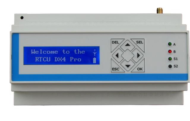
I've obtained an Remote Telemetry and Control Unit from Logic IO and I'll be playing with it in next few days/weeks. The RTCU DX4 pro is an GPRS-enabled control model for remote telemetry. The module is equipped with many cool functionalities (like iButton support) and several analog and digital IOs. It is programmed in some pseudo-pascal language and configured via USB. So stay tuned and wait for first effects.