piątek, 29 marca 2013

Short pulse generator, part 1.

Some time ago I have started designing an short pulse generator for time-resolved spectroscopy of electroluminescence. At first the design requirements were high, but after a market query, in search for devices capable of meeting these requirements they were lowered down significantly.

The sample for which this device is planned is a thin sheet of material suspended on an alumina frame, that acts as electrodes. We have measured DC I/V curve for the sample to assess the working parameters:


Therefore what we need is voltage of at least 35 V with current of at least 250 mA. In order to have an reserve in the parameters I assume that we need at least 40 V and 400 mA. For sake of simplicity I assume that the load of the device is almost purely resistive. Assesing the time parameters was a harder thing to do, so I assumes that the lower the better (the pulse time). Where is the limitation? In the power stage.

Using a simple generator, shown below, we are capable of generating a ~1 ns wide 5 V pulse with ease, using standard, from-the-shelf components. This could be even improved with faster ICs (comparators and AND gate.

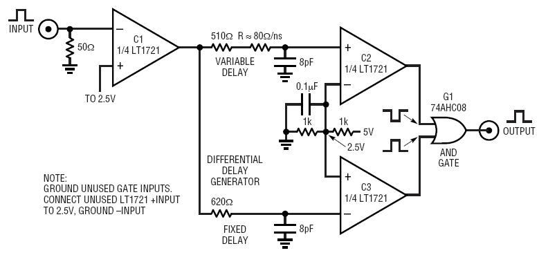
From this Linear application note.

But this circuit generates only 5 V pulses (or close to that, this is the power supply voltage of the output AND gate). Also, the current is very limited - to 10 mA, offered by a TTL gate. In order to improve these parameters we have to add an output power stage, that will have output current and maximal voltage on the level of the planned device and could be controlled by an TTL pulse. To meet these requirements I have chosen several routes to achieve that:

  • A set of parallel bipolar transistor put in the common base topology. This should allow to achieve high rise and fall time of the pulse, but a current of a single fast transistor is low (tens of mA) so I need to put lots of them in parallel and I am not convinced that this is totally safe and will not affect the working of the device.
  • A (most probably single) FET/MOSFET device. An easy scheme for achieving high currents, even of hundreds of amps, but the pulse time will be significantly longer. With a dedicated driver and chip-to-pcb mount some people achieved 25 ns pulse width, although with a current of 100 A (as soon as I find the paper I'll post a link here). A stand-alone mosfet usually will have a rise time of several ns and fall time of 100 ns or more.
  • A dedicted IC. A RF power amplifier or a MOSFET driver. The first type of ICs seems to be a good idea as it offers tens of GHz in bandwidth, although when I have looked closer in this matter it seems that such IC will only work good in a typical circuit, for example an WiFi amplifier or so. On the other hand, some MOSFET drivers, are capable of almost meeting my requirements. EL7158 from Intersil is capable of producing 12 A pulses with rise and fall time of 12 ns (with 2000 pF load). This gives a chance to produce a 25 or shorter ns pulse, although the voltage is limited up to 18 V. Although this is not the only such driver on the market...
So currently I'm on the stage of parts requirements stage. As soon as I get something new I will post it here for sure.

wtorek, 26 marca 2013

VMEBus crate - why not.

Recently I have acquired an VME CPU-Card and thought about testing it somehow. As after powering it up the card seemed to be alive I have decided to give it a shot and try to put together an VME crate.

For that I have used an old Eurorack that I have got from some phone central (or some similar telecommunications equipment). After checking that the size of the crate is standard I bought an backplane from e-bay for... 1 Euro (plus 12 for shipping, but that's not the case). Unfortunately only this backplanes are so cheap, regular VME equipment is pricey as hell.

So i have started from taking apart the old backplane:

And putting the new one:

Sorry for the mess. You can see that here the backplane is already in position, and connected to a power supply (it takes 5 V and +/- 12 V). The PSU is also taken from the same equipment that the crate is.


This (above) is the CPU card (on the left) with the display controller removed, and the display controller itself (on the right). The CPU Card is an Pentium 120 MHz with 64 MB RAM equipped with Universe Tundra VMEBus controller. Fortunately there are plenty of drivers for this PCItoVME bridge. The cards equipment covers a wide range of peripherals - starting from two serial and one parallel port, going through VGA, Ethernet and finishing with SCSI-II. The card has two PCI-compatible slots, one of which is occupied by the display controller. It also has an PC/104, ISA compatible socket. The SCSI, together with the FDD connector are on the P2 connector of the VMEBus, so I will have to make a special connector going from the P2 on the backside of the backplane  to the SCSI harddrive. As far as I have tested the CPU-card is fully functional so after I get some free time I will try to connect an SCSI HDD to this setup and install some Linux maybe. After that I plan to go back to few years ago when I was studying and try to re-learn VHDL in order to make some VME cards for this setup


wtorek, 19 marca 2013

IBM PS/2 Model 30-286

Some time ago I have bought this PC to finally have an 286 in my collection. It arrived a bit dirty but fully operational.


Although the case was a bit dirty the insides do not have much dust on them. It seems that the computer was stored in a rather nice place. The PC has a 286@10MHz CPU and around 1 meg of RAM. As this is obviously not enough formy taste I decided to add an RAM-card that was laying in my workshop from ome time. It seems to work, but gives 'only' 3712 KB of RAM. I guess this is only due to the jumper settings of the RAM-card, that I have to play with in the nearest future.


To enrich this machine even more and to allow it to have some connection to the outside world I have also added an Xircom Pocket Ethernet adapter (with RJ45 connector) to plug it to my ethernet at some point. A neat thing, that you may see here are the ports of that machine - keyboard and mouse uses PS/2 connectors which I find very convenient, when plugging it into my Compaq KVM (not so retro, I know).


As this machine is fully operational at the moment, with IBM-DOS on board (I do not remember the number) only thing that needs work here is the memory. The machine itself can take up to 4 megs of RAM on board, an the RAM-card should give additional 3 megs, making it 7 total - quite impressive for an 286. Additionally I plan to buy an 287 coprocessor and put it in, so I can try to test some calculations, why not. I have two more ISA slots so maybe I'll populate them with some other board in the future (a full-length data acquisition card would fit just right).

poniedziałek, 18 marca 2013

Latest project ;-)

So... my latest and most important project is here. Yesterday on 21:05 my wife gave birth to a healthy baby boy. And to imagine that this is only the beginning of a new journey...


Currently my wife and son are recovering in the hospital, which gives me some time to work on other, not-so-important stuff like old PCs so I'll post some updates on my blog somwhere soon, as later on probably I will not have any time to do that.

wtorek, 5 marca 2013

To PSoC or not to PSoC?

I have found several PSoC3 samples in my drawer recently... it seems that I have been planning to start learning to program these devices... why not? What do you think?

I have several CY8C3866 devices, but no programmer. As far as I know it is an JTAG programmed chip, so it should be fairly easy to put it together on my own.