piątek, 14 grudnia 2012

Electrode holder for a microscope

Today I finished making the blueprints of an electrode holder for an wide-field fluorescence microscope that we have at work. Nest week I'll take this to the workshop and I hope that they will quickly make the whole thing, so I can present it to you ;). And do some cool science of course.


I hope you like it. The electrode holder/manipulator consists of a base plate and top plate connected with springs and a micrometer head for controlling the height of the electrode that will be attached to the insulating teflon holder.

czwartek, 13 grudnia 2012

PC/104 DIO Card - final form

I have worked on the schematic of the digital I/O card based on the 82C55 for the SBC computer I have recently acquired and came with a final schematic - simplified as much as possible - and a PCB project. Here it is:


The schematic is simplified, yet it does comply with the PC/104 or ISA standard. There are three buffers - two for generic use - addresses and control signals (AEN, IOR, IOW, and RESET). Third buffer is utilized for data bus, and its control is a bit more tricky - the direction of the buffer is controlled by the buffered IOR signal and it is enabled by the ADDR signal that is generated in the addres decoder. For that part I have utilized a 8 bit comparator, so I can place the device in any address in the whole address space on 10 bits. Two LSB bits of the address are only buffered and feed to the 82C55 as it does all the magic. In that way I got rid of the strange address decoder of the old project and simplified generation of the Chip Select signal for the 82C55 - now it is selected by the ADDR signal from the address decoder.

The board layout is now much simpler with enough space to fit and DC25 connector, like shown below.

I plan to send the project soon to have PCBs made and start soldering the whole thing. I have several ideas how to use this PC, but can not say anything for now. I'll keep you informed :).

wtorek, 11 grudnia 2012

New machines, new plans.

Recently - last weekend - I was gifted with two new machines for my collection. One of them is a VIA EDEN SBC in the 3,5" form factor and the second is a PICMG 1.0 single card PC with a Pentium MMX.

The first machine has various industry features, like 4 COM ports, PC/104 interface and a completely fanless cooling. I plan to build several cards for the PC/104 interface (starting with the DIO card seen below). This way I will have an powerfull, ethernet-enabled machine booting from an Compac Flash card for managing the I/O features of any system. Below is the photo of the current state of the motherboard with the heatsink. Not very impressive, isn't it?


The second PC that I was gifted with is a PICMG 1.0 processor card with a Pentium MMX CPU. Accidentaly I had such backplane and a dedicated rackmount housing for such a card. Below is a photo of the whole set - the card in the housing. Currently only the power is connected to the board, as I had time only to check if the card is alive. The next step is to complete the whole interior - FDD, CD and a 2,5" HDD. I will probably put an DIO card inside, or leve the only ISA/PCI slot empty and waiting for 'better times' ;-).


The inventory page of my blog is also updated a bit, there is a summary of all the machines I currently have. I revise it from time to time.

PC/104 format DIO card


As I have recently got a PC/104 capable PC (VIA EDEN) I have thought about putting together a small Digital Input/Output (DIO) board for this. In my spare parts I have found some of the famous Intels 82C55 chips and in the internet I have found a quite good looking schematic.

http://technologyinterface.nmsu.edu/4_1/4_1s.html


This kind of interface is a typical application of an ISA device - U1 - U3 are the buffers for the ISA interface, U7 is the address decoder and U9 - U10 generate the /CS signal for the 8255 for all the four addresses (8255 has four addresses - three for three 8 bit ports and one for control word). U10 seems to be a bit spare, so I decided to get rid of it and to add a switch for the address decode. Still it seems to be a bit complicated, but you really need all that glue logic to force it to work good. You can always interface it directly to the ISA, but this is highly unrecommended.


After having the complete schematic I started routing the board. So now the first problems emerged - It is really hard to fit all these ICs into PC/104 size format. Really, really hard. And not to mention to rout everything! so this is how it looks for now.


I have to redesign it completely I guess - rip-up every trace and start from scratch, as I have forgot to place the SUBD connector, and put everything into the same layer... this is not the best solution, especially when you are limited only to a double sided printed circuit board.

For sure I will post some more info when I finish redesigning the PCB.

niedziela, 25 listopada 2012

Book-sized PC - alive.

I'm back after some time of being occupied by other tasks, that were not worthy of being published here ;-). I have completed my book-sized industrial PC.

I have received this machine some time ago from a friend of mine. It was used in his company in some complicated systems, and had it's BIOS exchanged for a custom one. This was the first and only big problem about this machine. I have tried exchanging the BIOS from the 'inside' using AWDFlash, but with no success, so I had to ask the same friend for more help - he burned the EEPROM with a proper BIOS *.bin file using a EEPROM burner. Now it worked, so I only had to install the OS (Win XP Proffesional SP2) and all drivers.


For this PC I have obtained (from ebay) a Nvidia Quadro NVS 200 PCI graphics card (64 MB) capable of feeding two VGAs (I'm currently using one, but plan to use two, why not). Apart from that - Pentium III 633 MHz (overclocked 550 MHZ Coppermine) and 512 MB of RAM (chipsets maximum unfortunately). The more interesting part of the PC is the I/O PCI card that I have added - seen on top. This is an DIO card (Digital I/O) - 16 relay inputs and 16 photo-isolated inputs. This will go very well with the whole array of ports the card has: four serials (RS-232/422/485 configurable), two parallels and two USBs.


The PC is quite compact, so I guess there will be some trouble with heat inside, especially when I will exchange the processor for a PIII Tualatin (preferably 1400 MHz PIII-S version) - this is the only upgrade that is still pending due to the lack of a suitable CPU, and general scarceness of such. Still this is a great addition to my collection and one of few that has potential application (but I do not want to say anything about that for now, as the grant proposal is sent but not graded by now). Next addition to this setup is a touch-screen LCD. It has a cool RS-232 interface, so it should not be hard to put it together. The harder part is to put the touch-screen part and the LCD part together without breaking anything. I have to find proper tape for mending it together and a foam spacer tape for making a spacer between the LCD and touch-screen.


I would like to thank again the 'anonymous' donors: of this machine and many more things ;-) for donating my collection with extremely nice hardware and helping me put it together.

poniedziałek, 20 sierpnia 2012

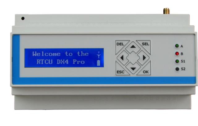
RTCU datalogger cont.

Okay, so as I wrote in the last post I had to modify the code in order to get any possibility apart from datalogging. I used asynchronous function blocks in order to get the 1-Wire communication in a separate thread-like entity.

 FUNCTION_BLOCK ASYNC Temp_DS1820;  
 VAR_INPUT  
   family : int;  
   kill : bool;  
 END_VAR;  
 VAR_OUTPUT  
   temp_calk, temp_ulam : int;  
 END_VAR;  

After that you have only to define a variable of type Temp_DS1820 and voila. To write the temperature into a file I use fsFileWriteStringNL and get the output variables out of the variable connected with the function block

 fsFileWriteStringNL(fd:=file_id, str:=temp="+intToStr(v:=temperature.temp_calk)+","+intToStr(v:=temperature.temp_ulam));  

Making the function block asynchronous makes it a separate thread without using a real thread. You only have to remember to put everything in the function block into a loop (I used while not kill do <...> end_while, so I can 'kill' this 'thread' whenever I want to) to work constantly.

This way I achieved ~15 times faster execution of the main program loop (that was only writing the temp into the file every 60 s) in the main program. This means that one can do tons of other things instead of waiting for ~700 ms to convert the temperature. Such approach can, of course, be used for various other applications that require the program to wait. RTCU DX4 is capable of multithreading so let's use it.

RTCU data logger

In this example I used a DS1820 1-Wire temperature sensor. The temperature is read from the sensor and written in a ASCII file on the SD-Card in the RTCU. Here's the code

 PROGRAM a1wire;  
 // These are the local variables of the program block  
 VAR  
   ow_dev : int;  
   sign : sint;  
   family : int;  
   dane_sint1, dane_sint2 : sint;  
   dane_int1, dane_int2 : int;  
   temp_calk, temp_ulam : int;  
   file_id : file;  
 END_VAR;  
   ow_dev:=owSearchX(first:=0, last:=255, reset:=true); // Scan the 1-Wire network  
   DebugMsg(message:=intToStr(v:=ow_dev)); // Number of 1-Wire devices in our case it is 1  
   family:=owGetFamily(device:=1); // Get the family name of the device  
   DebugMsg(message:=intToStr(v:=family)); // Family name of the device  
   DebugMsg(message:=owGetID(family:=family, device:=1)); // Get the 64bit ID of the device  
   if fsMediaPresent(media:=0) and (fsMediaOpen(media:=0)=0) then fsMediaQuickFormat(media:=0); fsDirCreate(name:="test"); fsDirChange(path:="A:\test"); fsFileClose(fd:=fsFileCreate(name:="test.txt")); fsMediaClose(media:=0); DebugMsg(message:="file created"); end_if; // if media is present and opened create a directory and go inside  
   fsMediaOpen(media:=0); // Open SD-Card  
   displayClear();  
 BEGIN  
   // Code from this point until END will be executed repeatedly  
   owAccess(family:=family, device:=1); // Acces the DS1820  
   owWrite(data:=16#44); // Order the DS1820 to convert temperature  
   Sleep(delay:=700); // Wait for 700 ms (DS1820 datasheet says tha this should be at least 750ms, but 700ms work for this particular DS1820)  
   owRelease(); // Release the 1-Wire network  
   owAccess(family:=family, device:=1); // Acces it again  
   owWrite(data:=16#BE); // Order the DS1820 to send the scratchpad content  
   owRead(data:=dane_sint1); // Read LSB   
   owRead(data:=dane_sint2); // Read MSB  
   if dane_sint1<0 then // Convert the temperature  
    sign:=64;   
    else   
      sign:=0;   
    end_if;  
   temp_calk:= shr8(in:=shl8(in:=dane_sint1, n:=1), n:=2)+sign;  
   if dane_sint2 <> 0 then // Get the sign of the temperature  
    temp_calk:=temp_calk*-1;   
    end_if;  
   temp_ulam:= 5*(dane_sint1 mod 2); // Calculate the fractional part of the temperature  
   owRelease(); // Release the 1-Wire network  
   if fsMediaOpen(media:=0)=0 then // Open the SD-Card  
    file_id := fsFileOpen(name:="a:\test\test.txt"); // Open file  
    if fsFileStatus(fd:=file_id) = 0 then // If file is opened...  
      DebugMsg(message:="file write status "+ intToStr(v:=fsFileWriteStringNL(fd:=file_id, str:="temp="+intToStr(v:=temp_calk)+","+intToStr(v:=temp_ulam)))); // ...write a string in it  
      fsFileClose(fd:=file_id); // Close the file  
      end_if;  
    end_if;  
   displayString(message:="temp="+intToStr(v:=temp_calk)+","+intToStr(v:=temp_ulam)); // Display the temperature  
 END;  
 END_PROGRAM;  

And it works! producing a test.txt file with

temp=28,0
temp=28,5
temp=28,5
etc...

Okay, that's great, but hey - I used the whole controller capacity for that. Every single run of the software takes ~1s (mainly due to the fact that I'm waiting for the temperature conversion for 700ms). So the next thing to do is to put the temperature reading from the 1-Wire sensor into a asynchronous functionblock or another thread, as this controller is able to multithread. Stay tuned for that, as I guess it will take me a bit to do ;-).

And I would like to thank Stanko, for help with calculating the temperature from the 1-Wire data :-).

piątek, 17 sierpnia 2012

RTCU front-panel keypad

In this example I use the front keypad to control an integer variable. Using up and down keys (codes 120 and 121) the user can increment and decrement the variable. Pressing ESC key (code 125) resets the variable to 0.


 PROGRAM keypad;  
 // These are the local variables of the program block  
 VAR  
 k : INT; //Key pressed on the front-panel keypad  
 x : INT; //Some number  
 END_VAR;  
 // The next code will only be executed once after the program starts  
   x := 0;  
   displayClear();  
 BEGIN  
 // Code from this point until END will be executed repeatedly  
   k := displayGetKey(timeout:=1);  
   if k = 120 then   
    x := x+1;   
    elsif k = 121 then   
      x := x-1;   
      elsif k = 125 then   
       x := 0;   
   end_if;  
   displayXY(x:=1, y:=1);  
   displayNumber(number := x);  
 END;  
 END_PROGRAM;  

The variable is displayed on the front-panel LCD using displayNumber() function, that is much easier to use when displaying only numbers, compared to displayString(message:=intToStr()) function combination. On the other hand when using the displayNumber one can not easily format the output with some markings, so I suggest sticking to the casting method (eg. casting the integer to string and adding some text markings). The output is similar, the displayNumber() example code takes 2658 bytes and  displayString(message:=intToStr()) takes 2712 bytes. Additional 54 bytes are occupied by the casting I guess, but this shouldn't be a big problem, when one realizes that the total memory for the configuration is up to 640 KB.

The next big thing - filesystem on the internal memory and on SD-card.

RTCU cont.

So I have started playing with the RTCU DX4 pro that I've mentioned earlier. The approach is quite new for me, as I'm used to drawing your software, instead of writing the code, as I'm usually programing in LabView. Also most of the automation engeineers is used to graphic programming, as most of the PLC software is 'drawn'. But... here we go.

Firstly - I have got an LCD in the unit. Screw blinking LEDs, lets do the classics:


 PROGRAM test_1;  
 // These are the local variables of the program block  
 VAR  
 END_VAR;  
 // The next code will only be executed once after the program starts  
 // displayClear();  
   displayPower(power:= ON);  
   displayXY(x:=1, y:=1);  
   displayString(message:="Hello world");  
   Sleep(delay:=3000);  
   displayClear();  
   an_out := 100;  

So - yay - the display works. Next thing is to display something more 'active', lets do a clock:


Okay. And next - add some status readings. In this cas the power supply voltage and temperature inside the module (and a mysterious number):


 BEGIN  
   // Code from this point until END will be executed repeatedly  
   clock();  
   displayXY(x:=1, y:=1);  
   displayString(message:="T "+sintToStr(v:=clock.hour)+":"+sintToStr(v:=clock.minute)+":"+sintToStr(v:=clock.second)+" ");  
   displayXY(x:=1, y:=2);  
   displayString(message:="V="+intToStr(v:=boardSupplyVoltage()/10)+" temp="+intToStr(v:=boardTemperature()/100));   
 END;  
 END_PROGRAM;  

The mysterious number is read from the front-panel keypad that I'm currently fighting with. Wihout using any kind of interrupts it's quite hard to have an keyboard input AND do some stuff in the same time. I mean - you can always multithread (this controller is capale of that) but wihout that it is not that simple, and there must be a trick to do that. Currently I do not know the trick so I'm stuck with that.

The clock() is a functionblock of clockGet type, that allows me to get to the real time clock in the device.

Tomorrow I'll try to interface with the SD-card inside and iButton memory on the dedicated 1-Wire line. If someone would need the codes for the upper examples I can publish them here. Source code posted for the upper examples and will be posted for all examples later.

czwartek, 16 sierpnia 2012

New toy

I've obtained an Remote Telemetry and Control Unit from Logic IO and I'll be playing with it in next few days/weeks. The RTCU DX4 pro is an GPRS-enabled control model for remote telemetry. The module is equipped with many cool functionalities (like iButton support) and several analog and digital IOs. It is programmed in some pseudo-pascal language and configured via USB. So stay tuned and wait for first effects.

środa, 18 lipca 2012

Still quite busy

Indeed, still I'm quite busy with other stuff and do not have any time to do a real update on the blog. I hope to be able to write something new this month and later, next month, when I'm back from vacation, to start updating this daily.

Not much progress was made recently, as I was in Austria for half a month. But now things should speed up a bit, as I'm going back to this device - http://www.nikodem.blogspot.com/2012/02/some-initial-evaluation.html as I plan to use it to digitize the data from my picoammeter.

czwartek, 14 czerwca 2012

Long time no see

No, no, I'm not dead. In the past one-and-a-half month I was quite busy with several thing - archaeological excavations and writing and submitting a grant application. Both of this things are completed right now, so I have some time for 'the stuff'.

Keep in touch as I will post some news very soon, probably tomorrow. In the mean time some new hardware was introduced into my collection, and I'm ready to install Operating Systems on some of the PCs. Also I'm quite near to finishing the picoammeter, so I'll post some sweet, sweet photos of my setup at work.

wtorek, 8 maja 2012

Small update

I'm still alive! Not much was done recently, but there were some minor changes in the Inventory. I've added more RAM to the 486 machine, now it has magnificent 64MB of RAM. On the other hand I took 2MB of 386 RAM in order to put it into the Sound Blaster AWE32 card that is fitted now in the 486 machine. Last but not least I've found a bracket to mount the HDD in the case of the 386, so now it has an SCSI drive.

As for the plans - I'm still waiting for another desktop AT case a friend of mine promised me ;-). When it will arrive I will be able to fit the 486 there. After that I will start installing stuff on the PCs - DOS 6.22 OR some linux (probably deli(cate) or some other, suitable for low-end computers). After instaling basic OS there will be time to install hardware goodies in the PCs - I/O card etc. I'll keep you all informed for sure.

In the mean time I have to fix my Amiga to have it 100% usable OR finish the 2MB chip hack I'm working on. Probably this will be the first thing I'll do, as it needs only to solder few wires and to put it back in the original case.

After all that I have an LCD with touchscreen to run, that a friend gave me. It will be fun to have a touchscreen with one of the PCs.

poniedziałek, 30 kwietnia 2012

Selling an Golden Image RC-1000


Finally, I've decided to get some free room at my desktop. I'm selling one of the Amiga RAM expansions I have - the Golden Image RC-1000. Good shape, little yellowed, fully working. ~ 50 Euros OVNO.


Here you can see also how my Amiga 500 looks like now.
Bare motherboard, lies proudly on the desk. Nothing fancy,
waiting to go back to the box OR finishing the 1,5MB ChipRAM trick somehow
(probably NOT, because my Agnus is not fat enough).


sobota, 14 kwietnia 2012

Building an 386 system


Sooo, finally I've put together 386 system that I've got from a guy that was cleaning his garage and getting rid of this machine. First of all I dismantled the whole computer and cleaned the housing. After that the battery on the motherboard was removed, because it was leaky. Electrolyte fortunately haven't done much damage so I've only had to clean the pcb.


After that I've soldered a new battery and put everything together. Although the motherboard has normal ISA slots this housing uses a riser card. This card is plugged into one of the 16 bit ISA slots and offers two 8 bit and three 16 bit ISA slots.


At the current moment the spec of this machine are: 386DX-40 and 16MB RAM. The graphics card is a Trident TVG9000 with 512k of RAM. In the computer you can also see SCSI controller. It's an AHA1540B with 50pin HDD interface (SCSI-1 and SCSI-2 compatible) and with 34pin FDD controller. Also in one of the 8bit slots I've put an I/O controller with serial, paralel and game ports - what a convienient usage of these ports. I still have to connect the floppies and HDD in order to install anything on this machine. After that I have an Scientific Solutions board ready for that PC. It's an 96 digital I/O card. I hope to run some parallel feed digital-to-analog converters on that.


As you can see I've added an second page for my blog called Inventory (see top). I plan to put there all the stuff that I have at home. At the current moment only some of the computers are fully described, the rest is waiting for the description or to be fixed/completed/put together.

czwartek, 12 kwietnia 2012

Box for ammeter

Only a samll update today - a full metal enclosure for the ammeter I'm making at the moment. A nice render for the end of the day:


This will be milled from aluminum. You can see three holes for output, power and sample polarization voltage. There is also a hole for input connector on the other side. For input, output and sample polarization I plan to use BNC connectors, and for the power connector a dedicated three pin military-style connector. I hope to have this machined soon, so I can finish mounting the whole thing.

Also a dedicated sample holder will be milled from non conductive Teflon:


On this image you can see an additional set of clamps with golden needles attached. The needles are used to make an electrical contact with the sample.

piątek, 30 marca 2012

Vacuum chamber for optical spectroscopy part 3

Okay, so I've got all the parts for the vacuum chamber and assembled the whole thing.


I've started by assembling the window. It is a 3mm quartz plate, sealed with two rubber o-rings (that will be later replaced with fluoride rubber ones)


After that I've screwed down the windows part to the chamber body, sealing this joint with another o-ring. To the vacuum flange an vacuum valve was fitted (Leybold full metal manual valve).


So assembly is done, now for testing it we attached the chamber to pumping station consisting of a rough vacuum pump and turbomolecular drag pump. Pumping station is attached via an metal flexible hose. The pump was left for ~1h to evacuate the chamber.


After one hour of pumping we achieved pressure equal to 1,6 *10e-5 mbar. It is quite good result for that pump. On a normal cryostat pumped for an hour we achieve 5,4*10e-5 mbar, so the results are comparable (the cryostat is slightly bigger). The only one thing to test is the vacuum tight sealing. I'll take a look at the chamber after some time to see if it's still under vacuum.

Some new stuff just arrived

So, I've got some fresh stuff from the workshop. Still in as-received state, but this is a big step for now. Just see how blue-prints turn into reality:

PCB for the ammeter arrived! Not yet populated, as I'm still waiting for the ICs (should be here next week). I hope that everything will fit, as some drills are smaller than expected


Sample holder is also ready. It turned out very nice. Maybe not exactly as in the render, but the crucial parts are ok. Also it is blackened, to limit light scattering from it.


Also the vacuum chamber parts are done, but I still have to put it together - expect some pictures soon.

czwartek, 15 marca 2012

Sample holder

Some viewers say that I'm getting lazy. To prove them wrong, recently I've drawn a sample holder, that I need to fix my samples in my measurement setup. When everything will be finished I post some pictures of the whole thing, but now - only a drawing from Autodesk Inventor :).


This thing will be used to fix an microscope slide (3" x 1") in a 3 axis stage from Thorlabs. The stage is motorized using linear motorized actuators, also from Thorlabs. This will allow me to automatize a big part of my measurements. Stay tuned.

piątek, 9 marca 2012

Reduction ring

I love showing nicely rendered pictures of my projects :3 so here is a small, yet very important thing - an ring with threads, for thread reduction. Outer ring is SM1, and inner is M18. It will allow me to mount a prism in my spectroscope, and this means that I will hove to show it to you as soon as I finish constructing it.


Making these one made me learn how to configure a new thread in Autodesk Inventor, because the SM1 thread is not defined in the software. I anyone would be interested I could make a simple tutorial for that.

Spectrometer will consist of a prism, mounted via this adapter, an an iDus CCD camera. This device is a 1024x256 px camera, designed for use as an spectrometer. I will post some specs later on, when I will show the whole device.

Amiga new PSU and some other new stuff.

I've managed to get some more free time and finished converting the Dell PSU to use it with my Amiga. I've added a simple switch to connect PS_ON to GND and a green LED on PWR_OK to signal if the PSU is working. Amiga is working decently on that, although I have not testet it yet under full load. I guess it shouldn't be a problem. The PSU can supply up to 15A on +5V and 12A on +12V lines. More than enough for my setup (with everything on).


At the moment my Amiga looks like that: 


Not very good indeed. I plan to put it together and mount the metal shielding (at least underneath the motherboard) as soon as I finish all the planned mods. On the left you can  the Protar A500HD, connected to the Amiga via side expansion slot (aka Zorro I). Unfortunately I've failed to run any RAM on it. I've tested like 30 pieces of SIMM memory (EDO and FPM, different size and timing) and none of them showed anything in CLI after AVAIL-ing the available memory. It seems that one realy need the Protar RAM sticks, that differ somehow from normal sticks. So this part of my plans is still a big fail. 
On the other hand I've got a new external FDD, that is lying under the Amiga, as seen in the photo above.
As you can see the trapdor expansion port is empty. It is because I've just received an KCS Power PC Board bought on Amibay.com:


I plan to install it as soon as I finish the 1MB Chip + 0,5MB Fast mod. I will have to solder a small pcb for generating control signals for the additional RAM in the expansion slot, as the Amiga will natively adress the 1MB of RAM that is soldered on the motherboard. KCS Power PC should add additional 0,5MB of Fast RAM and a RAM disk (?) or something ;). We'll se how it works, when it will work. At the moment putting the card in does not make any difference in anything, as the JP7A jumper is cut.

So, there are some plans for the future, concerning this region of my interests:
  • Finish the mod for using 1MB Chip on-board and 0,5MB Fast in the trapdoor (I'll be testing it firstly with other expansions).
  • Mount the metal shielding of the Amiga.
  • Try to run any RAM on the Protar.
  • Test and run the KCS Power PC.

wtorek, 6 marca 2012

Night work on Amiga hardware.

As you might remember, recently I've fried my Amiga PSU. Although I would like to repair it someday, at this moment I've decided to use an ATX PSU from a PC. I bought a PSU from a Dell GX280, because it's nice and slim and soldered the cable from the original Amiga PSU into the Dell one. I have to add a switch and some nice LED to have it complete and test it with my Amiga.

I'm in a hurry a little, because I'm getting a little unpatient with my Protar A500HD - a SCSI controller with Fast RAM. Althought it was working correctly on a ghetto version of the PSU (cables from the Amiga PSU sticked into an AT power supply connector) but the RAM was not working. This might be an issue with power supply quality - the AT PSU I'm using is not in the best condition possible and gives voltages that are not exactly correct, or with the RAM itself. Now I got over 20 different SIMMs to test them and a fancy new PSU - I hope that both will work and I'll manage to get the 8MB FastRAM :-).

No pictures today, but I will post some as soon as I get the ATX-Amiga Power Supply complete and my Amiga running (with 8MB FastRAM, I hope).

poniedziałek, 5 marca 2012

Precise ammeter part 2 1/2

I've found a better op-amp for I/V conversion - OPA129. This one has similar parameters to the LMC6081, but allows for using +-15V power supply, and swings up to 13V output. This means that for 10Mohm R1 resistor I can swing up to 130nA, and measure as low as 200pA (due to the fact that offset voltage of OPA129 is 2mV).


To lower the offset voltage at the OPA129 output I've used an datasheet-suggested offset correction, that consists of R5, R6, R7, R8 and C9. It allows to trimm the offset using a potentiometer R8. If this will allow to nullify the offset, I guess it should allow me to measure the current and order of magnitude lower, down to ~50pA, or even less - depending on how effective the offset correction will be.
The PCB design is not varying much from the previous one. I've only adjusted several things to match the requirements of the company that is making the PCB. The order was sent to them so in ~2 weeks I should have the board in my hands. I also ordered some elements for the board, including the most important ones: R1 and R3. As R1 I choose 10M 1% Beyschlag resistor with low temperature coefficient - only 50ppm. R3 is 20k 0,1% 15ppm resistor.
As I calculated Vout = Iin*R1*(R4)/(R3), as R4 consists of a resistor and a potentiometer I assume it will be exact 200k. With the said resistors I will get Vout=Iin*10^10, this means 1 volt per 100pA. R1 error is 10^9*1% = 100k and R3 error is 20R. Without temperature effects (when the circuit will be maintained at 25*C) measurement error equals to Iin*1,1*10e6. This is six orders of magnitude lower than the measurement, which is Iin*10e10.
As I want to limit the bandwidth at around 10kHz I'll have to calculate the capacitance of C1 and C8. C1 calculated is 1,6pF and C8 is 79,6pF. Closest values are 1.5pF and 82pF, and such capacitors I bought to use in the final device.
I also ordered both op-amps, so I'll have to wait only for all the parts to come and then I can solder the circuit and do some tests, so stay tuned.

czwartek, 1 marca 2012

Precise ammeter part 2

There has been some work done with the design of the picoammeter (I guess it can be called so). There were some slight changes in the schematic and PCB design. I guess that the first stage is nearing to an end.
I've removed R2 from the non-inverting input of the IC1, as there is no need for using it in a symmetrical supply design, and added capacitor in the feedback loop of the IC2A, to filter out any high frequency noise that might be generated in the first stage.

Most of the tracks were thickened up to 0,032 inch where possible and last, but not least, I've added a guard ring around the input of the IC1, what is, I guess, crucial for measuring lows currents (at least ALL application notes and datasheets say so and I do believe in that).

Bottom layer of the PCBTop layer of the PCB
 The board will be made at a professional workshop, with metalization and gold plating.
Bottom view render of the PCBTop view render of the PCB

Finishing the schematic and PCB design I did some calculations. In order to finish the project stage I've calculated the elements I'm going to use. Most important part - R1 - will be precise 1GΩ ± 1% or 10MΩ. Unfortunately I have not found (yet?) any ± 0,1% resistors with such big resistance, but I guess this will not be a big issue and we can deal with 1% error. For this resistance I will get 1mV/pA. The offset voltage of the LMC6081 is in order of 1mV, so I guess that minimum measurable current will be in order of tens of pA (counting in the noise etc). Maximum current is limited by maximum voltage output of the op-amp, +5V powered is around 4,7V which gives 4,7nA for R1=1GΩ maximum current for the given supply voltage. If I exchange the resistor with 10MΩ the range will shift to 1nA - 470nA. Unfortunately there is no 100MΩ resistors at my main supplier. Will have to evaluate this more.
The second part, consisting of the OPA2227 should work with gain around 10. With 20kΩ input impedance this means R4 around 200kΩ, which is very reasonable value, if you ask me. The main problem with this part is also output swing. As I'm planning to use the same supply as for the IC1, the output will be similarly limited, as the OPA2227 does not have rail-to-rail output. I can always use higher power supply voltage, but this will complicate the design much.
The dynamic part of the calculations is to be made, as I don't know at which frequency I should limit the bandwidth. Looking at datasheet for the LMC6081 I'm guessing somewhere around 1kHz. This should give reasonable settling time of the measurement and slightly lower the noise.
I would like to thank Mr. Michał Penkowski, from Gdansk Technical University for lots of information and help about such measurements.
Still lots of work to be done!

środa, 29 lutego 2012

Vacuum chamber for optical spectroscopy part 2

I've got some input from my friends and, what's more important, bosses approval of this project. Here it is how the chamber project looks like now (nice render isn't it?)


Now I'm making technical drawings from this to have it turned and milled at the workshop. This will be made from aluminum (unfortunately, as this is vacuum equipment and should be made from stainless steel), with quartz window and fluor-rubber o-rings for sealing.

wtorek, 28 lutego 2012

Precise ammeter - the begginig.

I've started recently designing an ammeter that would be suitable for measurement of very very very low currents. Probably at the level of 1..100 nanoamperes. I need such device for measuring photo-current at work. Currently the project looks like that:


First IC is LMC6081. This is an precision CMOS Operational Amplifier, the main advantage of this op-amp is its very high input impedance (it needs only 10fA for biasing, geez, how do they measure it?!?) and low offset voltage. In this application it works as an I-to-V converter. Bandwidth of this op-amp is limited by C1.
Second op-amp is an low noise precision op-amp that will be used for amplifying the output voltage to measurable level (with 1Mohm measuring resistor R1 the output of the I/V converter is 100mV for 100nA). Second part of the OPA2227 is just an buffer to provide stable output.
PCB design is a real pain in the neck, at the current moment it look like so:


I don't have any idea how to optimize it more, especially to lower any leakage current that might change the measurement. I'm counting for some creative input of several people that I've asked to help me design this module. I hope to post some more info soon.

piątek, 24 lutego 2012

Vacuum chamber for optical spectroscopy

I started designing an vacuum chamber for our spectroscopy setup at work to measure fluorescence at low pressure. I would like to share with you some early plans of it. This is an image that I made using Autodesk Inventor to show how it may look finished.


The body will be made of aluminum, the windows (far on the left) probably quarz. The NW25 flange on top is for connecting a vacuum valve and pump.

I hope my boss will like it :).

niedziela, 19 lutego 2012

Fried Amiga PSU

I have recently fried my Amiga powersupply, so until I don't manage to get a new one or repair this I will not be showing any Amiga goodnes. The good thing is that my Amiga is still alive (I've tested in on a AT PSU).

Okay, so from now the plans look like that:

  • Repair the PSU for Amiga.
  • Get some internet on the Linux Box to apt-get needed software (eg. setserial) and download the .adf's for Amiga.
  • Install AmigaOS 2.x on the Amiga (as now I have Kickstart 2.05 and probably will not change it for 3.1 now).
  • Run AmiTCP. Internet on A500 !!!oneone
  • Finish the plans for PAK68/3. I'm planning to make this accelerator for my Amiga, and now I'm at the beginning putting all the schematics into Eagle.
In the mean time:

  • Try to write some software for the AT90USB162 on the Intersil evaluation board. I've checked that it can be done. One can download the whole .hex file from the uC and program it with something else.
  • Have some fun with a rack. And Eurocard. More info soon.
  • I have some loudspeakers to repair. As this is part of a pending project the priority is high :).

poniedziałek, 13 lutego 2012

Linux Box, some serial buisness.

Yesterday I managed to get sme spare time to get a new computer up and running. This one is planned to be a Linux Box with various uses (for now it has one). The computer itself looks rather harmfull and compact: 


Inside there is a industrial motherboard in PICMG 1.3 standard with an backplane for 6 PCI-X cards. On the card - double Xeon 2,8 GHz and 1GB of ECC DDRAM. Sounds like enough for most of the things that I could be capable of imagining to do on such machine. Also I crammed an SCSI controller that will be mostly used to interface to 50pin disks that I use for the Amiga (as far as I know Linux is capable of mounting FFS and/or OFS file systems). As for software I went with Ubuntu Linux - probably out of laziness (as I had it on some Live CD). I've downloaded the newest distribution of the Ubuntu Server and just installed it on this machine. As the ethernet connection is not running on this machine (dunno' why, have to check it) I haven't installed anything more.


So, let's try to interface with the Amiga. I have connected both computers with a Nullmodem (a standard one, not some of the fancy 'ADF-transfer kits', that people are selling (price of a nullmodem x 10) and in fact these ARE normal nullmodems). So I chose some example file on my DH0, and typed in on the screen to see its content. After that I started the Linux Box and made it to start listening to the serial port (ttyS0):
cat /dev/ttyS0
This wat you will see it on the display, but yoy can redirect it to a file by using the >> {your file}. Then, on Amiga, I have sent the file over a serial:
type {your file} to ser:


As you can see - it works. It works accidentally as I have not done anything to set the serial port parameters, both computers are working in the default settings. I have to install setserial on the Linux Box to be able to configure the serial port, and in order to do that I have to have an internet connection on it up and running, so I guess it's the closest thing that I will be doing.